Emulating Enigma
V. Hunter Adams (vha3@cornell.edu)
TLDR: This webpage gives on overview of the Enigma Machine's design, presents software that emulates an Enigma machine, and then demonstrates running that software on a PIC32 microcontroller to encipher and decipher messages.
import numpy
import matplotlib.pyplot as plt
from IPython.display import Audio
from IPython.display import Image
from scipy import signal
from scipy.fft import fftshift
from scipy.io import wavfile
plt.rcParams['figure.figsize'] = [12, 3]
from IPython.core.display import HTML
HTML("""
<style>
.output_png {
    display: table-cell;
    text-align: center;
    vertical-align: middle;
}
</style>
""")
HTML('''<script>
code_show=true;
function code_toggle() {
 if (code_show){
 $('div.input').hide();
 } else {
 $('div.input').show();
 }
 code_show = !code_show
}
$( document ).ready(code_toggle);
</script>
<form action="javascript:code_toggle()"><input type="submit" value="Click here to toggle on/off the raw code."></form>''')
Webpage table of contents
Background and Introduction
The Enigma machine is an interesting example of historical, high-stakes, geopolitical electrical engineering. It is a rotary-electric enciphering machine that can be used to convert a string of readable plaintext into a string of garbled ciphertext. It was invented by a German engineer, Arthur Scherbius, shortly after WWI. A number of governments adapted the Enigma for encoding their communications, but it was used most famously and extensively by Nazi Germany.
A string of plaintext typed into an Enigma machine became a string of ciphertext. This ciphertext could only be translated back into plaintext by someone else that also had an Enigma machine, and that knew how to configure the Enigma machine to decipher that particular message. If an Enigma machine were setup with the wrong configurations, a string of ciphertext would just produce more garbled nonsense. The security of the device came from the number of possible configurations. The device was constructed such that there were over $1.07 \times 10^{23}$ possible configurations. Of these, only one would translate the ciphertext into readable plaintext. With this number of configurations, even if you could test one configuration every millisecond, it would take longer than the age of the universe to exhaustively search every configuration. And furthermore, these configurations would change every day. For these reasons, the Germans believed Enigma to be unbreakable. German military strategy going into WWII involved very fast tactics, which needed to be coordinated over radio. The Germans knew that these radio transmissions would be intercepted, so they encoded the transmissions using Enigma machines.
It turns out that the Enigma had a fatal flaw which would be exploited, enabling Allied codebreakers at Bletchley Park and elsewhere to build a machine that could crack Enigma every day. The effort to crack Enigma is famously known as Project ULTRA, and the machine that they built to crack it is the Bombe. The Bombe is arguably one of the most historically impactful machines that has ever been built. But that's the subject of a separate discussion.
The Enigma Design
Overview
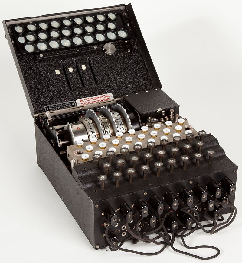
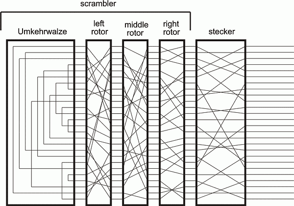
Superficially, the Enigma machine looks a lot like a typewriter. It features a familiar-looking keyboard on top, but with some additional components that are best understood by looking the schematic. I borrowed this schematic from Graham Ellsbury's website, which is linked here and referenced below.
Just above the keyboard in the picture on below, you can see three rows of what appear to be lightbulbs. This is the lampboard, and underneath each of those lightbulbs was a letter of the alphabet (26 bulbs for 26 letters). When an operator pressed a key on the keyboard, an electrical circuit would be closed to cause one of the lights on the lampboard to illuminate. This would be the enciphered character for that key entry. The user would then press another key, and some other (or, possibly, the same) lamp would illuminate, giving them the next character in the cipher.
The Enigma was incredibly difficult to crack for two reasons:
- The specific circuits that connected key entries to lampboard outputs depended on the configuration of the steckerboard and rotors (each of which will be discussed momentarily), of which there were way too many to exhaustively search, and which changed from day to day.
- The internal circuitry changed with every keypress. The rotors inside the Enigma machine would rotate each time the user pressed a key, completely changing the internal circuitry. So, if a user keyed the string
AAAAAinto the machine, they would not get a string of 5 of the same characters back out. I setup the emulator with some arbitary configurations and keyed inAAAAA. The machine returned the cipherRBUEL.
The Steckerboard
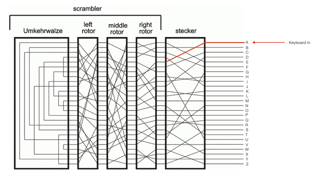
On the front of the Enigma, you can see a bunch of sockets, some of which are connected to one another by pluggable wires. This is called the "steckerboard" (also called the "plugboard"). It is reconfigurable, and it maps a particular key to some other key before sending it through the rest of the internal circuitry of the device. In the schematic shown on the right, the keyboard is represented by the 26 wires entering on the right side of the diagram. Each of these wires passes through the steckerboard. Depending how the steckerboard is configured, a particular key might get mapped to a different key. In the diagram, for example, the steckerboard maps "A" (the top wire) to "E" (the fifth wire) as shown below.
An operator would make 10 connections on the steckerboard. That is to say, 10 letters would be mapped to other letters by the steckerboard. The remaining 6 letters would be mapped to themselves, like "B" in the diagram above.
A critical flaw of the Enigma machine is that this steckerboard is reciprocal. If the steckerboard maps "A" to "E", then it also maps "E" to "A". The reciprocal nature of the steckerboard is not required for the Enigma machine to work, but it is a feature which was exploited by Turing and others to crack the ciphers.
The Rotors
Electrical current would then pass through three rotors. Like the stecker, each of these rotors would map a particular input wire (representing a character) to an output wire (representing another character). Unlike the steckerboard, the internal connections of these rotors were not reconfigurable. However, they could be placed in the machine in any order, and there were more than 3 rotors from which to choose. So, part of the configuration of the Enigma involved putting the correct 3 rotors into the machine, in the correct order, and in the correct orientation.
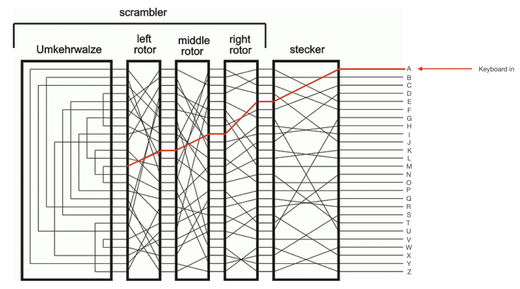
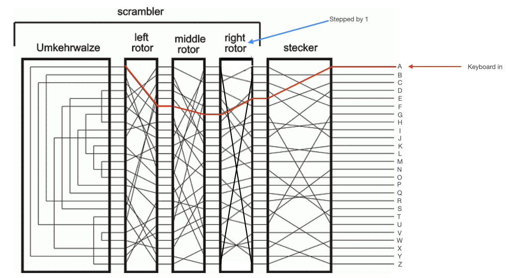
To further comlicate things, each of these rotors rotated. The right rotor would move one step every time a key was pressed. The middle motor would move one step every time the right rotor completed a full rotation, and the left rotor would move one step every time the middle rotor completed a full rotation. This meant that repeated inputs did not yield repeated outputs. The internal circuitry of the Enigma changed with every keypress. This is illustrated in the diagrams below, which show the path through the stecker and rotors taken by two sequential presses of 'A'. After the first press, the right rotor moves one step.
The Umkehrwalze
The Umkerhwalze sat to the left of the left (slowest) rotor. This was a static device which acted simply like a collection of 13 wires. Each wire connected two of its input pins, so that current flowing in one pin would be reflected back out another pin. This reflected current would then make its way back through the rotors and stecker, as shown in the diagrams below.
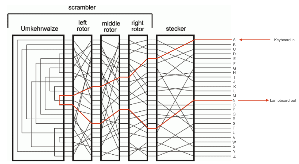
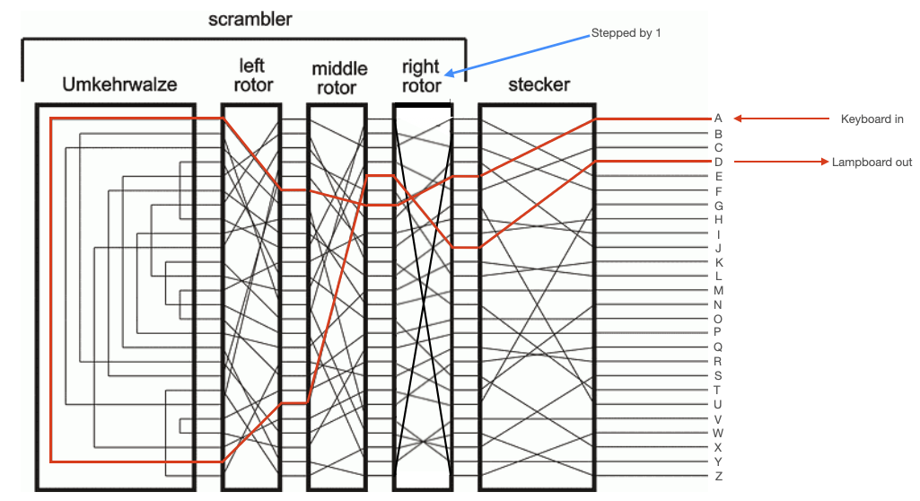
NOTE: From the above diagram, the reciprocal nature of the Enigma is apparent. You can see that, for the first keypress, pressing 'N' would have yielded 'A' lampboard output. In the second keypress, pressing 'D' would have yielded 'A' lampboard output. So, if the recipient of a message setup their machine correctly, they could simply key in the cyphertext and the Enigma would output the plaintext message.
Using the Enigma
The procedure for enciphering and deciphering a message is written out here. It is also demonstrated in the video at the end of this webpage.
Enciphering
- The Enigma operator consults their provided codebook, and configures the steckerboard and rotors in accordance with that date's specifications.
- The operator consults their codebook, and rotates the rotors to the correct indicator setting. The indicator setting tells the operator which characters on each rotor should be rotated to be facing directly upward.
- The operator then thinks up a random 3-character sequence that they will use to encipher their message. They code this sequence into the Enigma, and they write down the output sequence. For example, the operator may decide to encipher their message using the sequence
EVN. They would keyEVNinto the Enigma and some other sequence, perhapsSDKwould be output from the Enigma. The operator would take note of the sequenceSDK. In this example,EVNis the "message setting" andSDKis the "enciphered message setting." - The operator would then rotate the rotors in the machine so that their chosen message setting,
EVN, was facing directly upward. The machine is now ready for enciphering. - The operator would key the plaintext into the machine, and record the ciphertext. For example, they may key in
HELLOWORLDand it would be enciphered toONENUUNPOX. - The operator would then send both the enciphered message setting, and the enciphered message.
Deciphering
- The receiving Enigma operator would have the same codebook in their posession as the sender, and would configure their Enigma machine in accordance to that date's specifications (which would be exactly the same as those that the sender used).
- The operator would then key in the enciphered message setting
SDK. Because of the reciprocal nature of the Enigma, this would outputEVN, the message setting that the sender used to encode their message. - The operator would then rotate the rotors in the machine so that the deciphered message setting,
EVN, was facing directly upward. The machine is now ready for deciphering. - The operator would key the ciphertext into the machine, and write down the plaintext returned by the machine. In this example, the operator would key in
ONENUUNPOXand the machine would outputHELLOWORLD.
Note that the Enigma did not support spaces, punctuation, or lower case letters. The character X was sometimes used to represent a space, if there was any ambiguity.
Emulating the Enigma in C
The C-code below emulates an Enigma machine. The stecker settings, rotor connections, and umkehrwalze settings are hardcoded in the code, but can be reconfigured by the user through the command line. When run, the code will ask the user for the rotor settings (i.e. the indicator or message settings). It then asks the user for a message, which it enciphers. This code will both encipher and decipher messages. Build with gcc eof.c -o eof.
This code takes advantage of the fact that the ASCII codes for the characters A-Z are sequential. ASCII A is 65, ASII B is 66, etc. to ASCII Z which is 90. So, we can emulate the mapping from character to character that is done by the stecker, rotors, and umkehrwalze by adding and subtracting from the ASCII representations for each character (being careful to wrap at Z back to A).
//
// C emulator for an Enigma Machine with 3 rotors
// Hunter Adams (vha3@cornell.edu)
//
// gcc eof.c -o eof
//
#include <stdio.h>
#include <string.h>
// EXAMPLE SETTINGS FROM DIAGRAM FOUND ONLINE
// stecker: EBFJACUIHDLKMTOPRQXNGVZSYW - Arbitrary (though must be reciprocal)
// rotor 1: EKMFLGDQVZNTOWYHXUSPAIBRCJ - ROTOR I from online
// rotor 2: AJDKSIRUXBLHWTMCQGZNPYFVOE - ROTOR II from online
// rotor 3: BDFHJLCPRTXVZNYEIWGAKMUSQO - ROTOR III from online
// umkehrw: YRUHQSLDPXNGOKMIEBFZCWVJAT - Non-rotatable Umkehrwalze B from online
char STECKER [27]  = {4,0,3,6,22,23,14,1,25,20,1,25,0,6,0,0,1,25,5,20,12,0,3,21,0,23,0};
char ROTOR1  [27]  = {4,9,10,2,7,1,23,9,13,16,3,8,2,9,10,18,7,3,0,22,6,13,5,20,4,10,0};
char ROTOR2  [27]  = {0,8,1,7,14,3,11,13,15,18,1,22,10,6,24,13,0,15,7,20,21,3,9,24,16,5,0};
char ROTOR3  [27]  = {1,2,3,4,5,6,22,8,9,10,13,10,13,0,10,15,18,5,14,7,16,17,24,21,18,15,0};
char UMKEHR  [27]  = {24,16,18,4,12,13,5,22,7,14,3,21,2,23,24,19,14,10,13,6,8,1,25,12,2,20,0};
// variables to hold rotor positions
volatile int count1, count2, count3 ;
// Maximum size of the message that can be encoded (in character)
#define MAXINPUT 60

// sets rotor positions
void setRotor() {
    char value [5] ;
    printf("\nInput rotor positions (e.g. RNF): ") ;
    scanf("%s", value) ;
    count3=(value[0] - 'A');
    count2=(value[1] - 'A');
    count1=(value[2] - 'A');
}

// allows custom configuration of stecker, rotors, or umkehrwalze
void setElement(int classifier) {
    char peg = 'A' ;
    char c[27] ;
    char temp [27] ;
    int i ;

    switch (classifier)
    {
        case 0:
            printf("\nInput stecker table: \n") ;
            break ;
        case 1:
            printf("\nInput rotor 1 table: \n") ;
            break;
        case 2:
            printf("\nInput rotor 2 table: \n") ;
            break;
        case 3:
            printf("\nInput rotor 3 table: \n") ;
            break;
        case 4:
            printf("\nInput umkehrwalze table: \n") ;
            break;
        default: printf("Invalid") ;
    }
    scanf("%s", c) ;

    while (peg <= 'Z') {
        int value = c[peg - 'A'] - peg ;
        if (value<0) value += ('Z' - 'A' + 1) ;

        switch (classifier)
        {
            case 0:
                STECKER[peg-'A'] = value;
                break;
            case 1:
                ROTOR1[peg-'A'] = value;
                break;
            case 2:
                ROTOR2[peg-'A'] = value;
                break;
            case 3:
                ROTOR3[peg-'A'] = value;
                break;
            case 4:
                UMKEHR[peg-'A'] = value;
                break;
            default:
                printf("Invalid"); break;
        }
        peg += 1 ;
    }

    switch (classifier)
        {
            case 0:
                printf("Stecker settings: \n") ;
                for (i=0; i<27; i++) {
                    printf("%d ", STECKER[i]) ;
                }
                break;
            case 1:
                printf("Rotor 1 settings: \n") ;
                for (i=0; i<27; i++) {
                    printf("%d ", ROTOR1[i]) ;
                }
                break;
            case 2:
                printf("Rotor 2 settings: \n") ;
                for (i=0; i<27; i++) {
                    printf("%d ", ROTOR2[i]) ;
                }
                break;
            case 3:
                printf("Rotor 3 settings: \n") ;
                for (i=0; i<27; i++) {
                    printf("%d ", ROTOR3[i]) ;
                }
                break;
            case 4:
                printf("Umkehrwalze settings: \n") ;
                for (i=0; i<27; i++) {
                    printf("%d ", UMKEHR[i]) ;
                }
                break;
            default:
                printf("Invalid"); break;
        }
}

char forwardElement(char Element [27], char input, int countval) {
    // Get the index
    int index = input - 'A' + countval;
    // Make sure the index wraps at 25
    if (index>25) index = (index%26);
    // Update the character value with value at that index
    char output = (input + Element[index]);
    // Range check for values above Z, wrap to A
    if (output>90) output=((output%('Z'+1))+'A');
    // Return value
    return output ;
}


char reverseElement(char Element [27], char output, int countval) {
    // Start at char value 1 below A, outval 0, index 0
    char testval = 'A'-1 ;
    char outval = '0' ;
    int index = 0 ;
    // While the output value does not equal the desired output value
    while (outval != output) {
        // Increment the test character
        testval += 1 ;
        // Get the index of the character
        index = testval - 'A' + countval;
        // Make sure the index wraps at 25
        if (index>25) index = (index%26);
        // Update the test output value with the value at that index
        outval = (testval + Element[index]) ;
        // Range check for values above Z, wrap to A
        if (outval>90) outval=((outval%('Z'+1)) + 'A') ;
    }
    // Return the character that yielded desired output
    return testval ;
}


int main() {
    char c;
    char user_in[MAXINPUT] ;
    char user_out[MAXINPUT] ;
    int i ;
    printf("\n\nAt any time, press 'r' to set rotor configurations and 't' for a total reconfig.\n\n");

    setRotor() ;
    // Wait for keyboard entry
    printf("\nInput value (all caps no spaces): ");
    while(1) {
        // Get input
        scanf("%s", user_in) ;
        memset(user_out, 0, MAXINPUT) ;
        int j = 0 ;
        // Grab first character
        c = '0' ;
        while (j<strlen(user_in)) {
            c = user_in[j] ;
            if (c=='\r') break ;
            else if (c=='r') setRotor() ;
            else if (c=='t') {
                setElement(0);
                setElement(1);
                setElement(2);
                setElement(3);
                setElement(4);
                setRotor() ;
            }
            else {
                // COMMENT-IN THE PRINT STATEMENTS BELOW TO SEE
                // THE VALUE THAT IS ATTAINED IN EACH STEP OF THE
                // ENCODING CIRCUIT
                //
                // printf("\nInput value: %c", c);
                // Forward stecker
                char value2 = forwardElement(STECKER, c, 0) ;
                // printf("\nStecked value: "); putchar(value2) ;
                // Forward rotor 1
                char value3 = forwardElement(ROTOR1, value2, count1) ;
                // printf("\nRotorized value 1: "); putchar(value3) ;
                // Forward rotor 2
                char value4 = forwardElement(ROTOR2, value3, count2) ;
                // printf("\nRotorized value 2: "); putchar(value4) ;
                // Forward rotor 3
                char value5 = forwardElement(ROTOR3, value4, count3) ;
                // printf("\nRotorized value 3: "); putchar(value5) ;
                // Umkehrwalze
                char value6 = forwardElement(UMKEHR, value5, 0) ;
                // printf("\nUmkehrwalze value: "); putchar(value6) ;

                // print the rotor count1
                // printf("\nRotor count1: %d", count1) ;
                // print the rotor count2
                // printf("\nRotor count2: %d", count2) ;
                // print the rotor count3
                // printf("\nRotor count3: %d", count3) ;

                // Reverse Rotor 3
                char value7 = reverseElement(ROTOR3, value6, count3) ;
                // printf("\nRev. rotor value 3: "); putchar(value7) ;
                // Reverse Rotor 2
                char value8 = reverseElement(ROTOR2, value7, count2) ;
                // printf("\nRev. rotor value 2: "); putchar(value8) ;
                // Reverse Rotor 1
                char value9 = reverseElement(ROTOR1, value8, count1) ;
                // printf("\nRev. rotor value 1: "); putchar(value9) ;
                // Reverse stecker
                char value10 = reverseElement(STECKER, value9, 0) ;
                // printf("\nStecker Output: "); putchar(value10) ;

                user_out[j] = value10 ;

                // Iterate the rotor counters
                count1 = ((count1+1) % 26) ;
                if (count1==0) count2 = ((count2+1)%26) ;
                if ((count1==0)&&(count2==0)) count3 = ((count3+1)%26) ;
            }
            j += 1 ;
        }

        printf("\n\n%s\n\n", user_out) ;

        // Get a new input value
        printf("\n\nInput value (all caps no spaces): ");
    }
}
Enigma on the PIC32
I ported the above C code to the PIC32 microcontroller, and setup a Python user interface that somewhat simulates the experience of using a physical Enigma. The video below shows a demonstration of enciphering and deciphering a message.
Note: Please email me for the PIC32 code. I may use this as a laboratory assignment in a class, so I'm not posting the code here.
Resources