Dual-core Direct Digital Synthesis (DDS) on RP2040 (Raspberry Pi Pico)
V. Hunter Adams (vha3@cornell.edu)
Objective and page organization
This project was meant to provide an objective thru which to build understanding of multicore capabilities on the RP2040. For this project, I instantiated a timer interrupt on both core 0 and core 1. Direct digital synthesis is performed separately on each core, and each core writes to a separate channel of the SPI DAC. The consequence is that the A output of the DAC is an an 800 Hz sine wave being generated on core 1, and the B output of the DAC is a 400 Hz sine wave being generated on core 0. A simple state machine amplitude-modulates these sine waves to 1Hz "beeps" using Fixed Point arithmetic. Because the RP2040 buffers SPI writes, no spinlock is required to control each core's access to the SPI channel.
A spinlock is used in the main program of each core to control access to a global variable. Each core locks the variable, increments it by 10 (printing as it does so), and then unlocks it so that the other core can lock/increment. Experimentation shows that a small delay is required after unlocking for the other core to reliably take control of the spinlock.
All of the code is provided in a listing in the first section of this page. The rest of the page walks through the C source file from top to bottom, explaining each line of code. Lastly, I've included some plots output plots from the oscilloscope and compared the measured output frequencies to the expected output frequencies.
All the code
/**
 * V. Hunter Adams (vha3@cornell.edu)

    This is an experiment with the multicore capabilities on the
    RP2040. The program instantiates a timer interrupt on each core.
    Each of these timer interrupts writes to a separate channel
    of the SPI DAC and does DDS of two sine waves of two different
    frequencies. These sine waves are amplitude-modulated to "beeps."

    No spinlock is required to mediate the SPI writes because of the
    SPI buffer on the RP2040. Spinlocks are used in the main program
    running on each core to lock the other out from an incrementing
    global variable. Experimentation shows that a short delay is
    required between unlocking and locking the spinlock for the second
    core to reliably lock the spinlock before the first re-locks it.

    Note that globals are visible from both cores. Note also that GPIO
    pin mappings performed on core 0 can be utilized from core 1.
    Creation of an alarm pool is required to force a timer interrupt to
    take place on core 1 rather than core 0.

 */

#include <stdio.h>
#include <math.h>
#include "pico/stdlib.h"
#include "pico/multicore.h"
#include "hardware/sync.h"
#include "hardware/spi.h"

// === the fixed point macros ========================================
typedef signed int fix15 ;
#define multfix15(a,b) ((fix15)((((signed long long)(a))*((signed long long)(b)))>>15))
#define float2fix15(a) ((fix15)((a)*32768.0))
#define fix2float15(a) ((float)(a)/32768.0)
#define absfix15(a) abs(a)
#define int2fix15(a) ((fix15)(a << 15))
#define fix2int15(a) ((int)(a >> 15))
#define char2fix15(a) (fix15)(((fix15)(a)) << 15)
#define divfix(a,b) (fix15)( (((signed long long)(a)) << 15) / (b))

//DDS parameters
#define two32 4294967296.0 // 2^32
#define Fs 40000
// the DDS units - core 1
volatile unsigned int phase_accum_main_1;
volatile unsigned int phase_incr_main_1 = (800.0*two32)/Fs ;
// the DDS units - core 2
volatile unsigned int phase_accum_main_0;
volatile unsigned int phase_incr_main_0 = (400.0*two32)/Fs ;

// DDS sine table
#define sine_table_size 256
fix15 sin_table[sine_table_size] ;

// Values output to DAC
int DAC_output_0 ;
int DAC_output_1 ;

// Amplitude modulation parameters and variables
fix15 max_amplitude = int2fix15(1) ;
fix15 attack_inc ;
fix15 decay_inc ;
fix15 current_amplitude_0 = 0 ;
fix15 current_amplitude_1 = 0 ;
#define ATTACK_TIME             200
#define DECAY_TIME              200
#define SUSTAIN_TIME            10000
#define BEEP_DURATION           10400
#define BEEP_REPEAT_INTERVAL    40000

//SPI data
uint16_t DAC_data_1 ; // output value
uint16_t DAC_data_0 ; // output value

//DAC parameters
// A-channel, 1x, active
#define DAC_config_chan_A 0b0011000000000000
// B-channel, 1x, active
#define DAC_config_chan_B 0b1011000000000000

//SPI configurations
#define PIN_MISO 4
#define PIN_CS   5
#define PIN_SCK  6
#define PIN_MOSI 7
#define LDAC     8
#define SPI_PORT spi0

// Two variables to store core number
volatile int corenum_0  ;
volatile int corenum_1  ;

// Global counter for spinlock experimenting
volatile int global_counter = 0 ;

// Counter spinlock
int spinlock_num_count ;
spin_lock_t *spinlock_count ;

// State machine variables
volatile unsigned int STATE_0 = 0 ;
volatile unsigned int count_0 = 0 ;
volatile unsigned int STATE_1 = 0 ;
volatile unsigned int count_1 = 0 ;

// This one is called on core 1
bool repeating_timer_callback_core_1(struct repeating_timer *t) {

    if (STATE_1 == 0) {
        // DDS phase and sine table lookup
        phase_accum_main_1 += phase_incr_main_1  ;
        DAC_output_1 = fix2int15(multfix15(current_amplitude_1,
            sin_table[phase_accum_main_1>>24])) + 2048 ;

        // Ramp up amplitude
        if (count_1 < ATTACK_TIME) {
            current_amplitude_1 = (current_amplitude_1 + attack_inc) ;
        }
        // Ramp down amplitude
        else if (count_1 > BEEP_DURATION - DECAY_TIME) {
            current_amplitude_1 = (current_amplitude_1 - decay_inc) ;
        }

        // Mask with DAC control bits
        DAC_data_1 = (DAC_config_chan_A | (DAC_output_1 & 0xffff))  ;

        // SPI write (no spinlock b/c of SPI buffer)
        spi_write16_blocking(SPI_PORT, &DAC_data_1, 1) ;

        // Increment the counter
        count_1 += 1 ;

        // State transition?
        if (count_1 == BEEP_DURATION) {
            STATE_1 = 1 ;
            count_1 = 0 ;
        }
    }

    // State transition?
    else {
        count_1 += 1 ;
        if (count_1 == BEEP_REPEAT_INTERVAL) {
            current_amplitude_1 = 0 ;
            STATE_1 = 0 ;
            count_1 = 0 ;
        }
    }

    // retrieve core number of execution
    corenum_1 = get_core_num() ;

    return true;
}

// This one is called on core 0
bool repeating_timer_callback_core_0(struct repeating_timer *t) {

    if (STATE_0 == 0) {
        // DDS phase and sine table lookup
        phase_accum_main_0 += phase_incr_main_0  ;
        DAC_output_0 = fix2int15(multfix15(current_amplitude_0,
            sin_table[phase_accum_main_0>>24])) + 2048 ;

        // Ramp up amplitude
        if (count_0 < ATTACK_TIME) {
            current_amplitude_0 = (current_amplitude_0 + attack_inc) ;
        }
        // Ramp down amplitude
        else if (count_0 > BEEP_DURATION - DECAY_TIME) {
            current_amplitude_0 = (current_amplitude_0 - decay_inc) ;
        }

        DAC_data_0 = (DAC_config_chan_B | (DAC_output_0 & 0xffff))  ;

        // SPI write (no spinlock b/c of SPI buffer)
        spi_write16_blocking(SPI_PORT, &DAC_data_0, 1) ;

        // Increment the counter
        count_0 += 1 ;

        // State transition?
        if (count_0 == BEEP_DURATION) {
            STATE_0 = 1 ;
            count_0 = 0 ;
        }
    }

    // State transition?
    else {
        count_0 += 1 ;
        if (count_0 == BEEP_REPEAT_INTERVAL) {
            current_amplitude_0 = 0 ;
            STATE_0 = 0 ;
            count_0 = 0 ;
        }
    }

    // retrieve core number of execution
    corenum_0 = get_core_num() ;

    return true;
}

void core1_entry() {

    // create an alarm pool on core 1
    alarm_pool_t *core1pool ;
    core1pool = alarm_pool_create(2, 16) ;

    // Create a repeating timer that calls repeating_timer_callback.
    struct repeating_timer timer_core_1;

    // Negative delay so means we will call repeating_timer_callback, and call it
    // again 25us (40kHz) later regardless of how long the callback took to execute
    alarm_pool_add_repeating_timer_us(core1pool, -25,
        repeating_timer_callback_core_1, NULL, &timer_core_1);

    while (1) {

        // Lock spinlock (without disabling interrupts)
        spin_lock_unsafe_blocking(spinlock_count) ;
        // Increment global counter variable
        for (int i=0; i<10; i++) {
            global_counter += 1 ;
            sleep_ms(250) ;
            printf("Core 1: %d, ISR core: %d\n", global_counter, corenum_1) ;
        }
        printf("\n\n") ;
        // Unlock spinlock
        spin_unlock_unsafe(spinlock_count) ;
        // A short delay to make sure the other core unlocks the spinlock
        // before this one unlocks it again (experimentation shows that
        // this is necessary)
        sleep_ms(1);

    }
}

int main() {
    // Initialize stdio/uart
    stdio_init_all();
    printf("Hello, multicore!\n");

    // Initialize SPI channel (channel, baud rate set to 20MHz)
    spi_init(SPI_PORT, 20000000) ;
    // Format (channel, data bits per transfer, polarity, phase, order)
    spi_set_format(SPI_PORT, 16, 0, 0, 0);

    // Map SPI signals to GPIO ports
    gpio_set_function(PIN_MISO, GPIO_FUNC_SPI);
    gpio_set_function(PIN_SCK, GPIO_FUNC_SPI);
    gpio_set_function(PIN_MOSI, GPIO_FUNC_SPI);
    gpio_set_function(PIN_CS, GPIO_FUNC_SPI) ;

    // Map LDAC pin to GPIO port, hold it low
    gpio_init(LDAC) ;
    gpio_set_dir(LDAC, GPIO_OUT) ;
    gpio_put(LDAC, 0) ;

    // set up increments for calculating bow envelope
    attack_inc = divfix(max_amplitude, int2fix15(ATTACK_TIME)) ;//max_amplitude/(float)ATTACK_TIME ;
    decay_inc =  divfix(max_amplitude, int2fix15(DECAY_TIME)) ;//max_amplitude/(float)DECAY_TIME ;

    // === build the sine lookup table =======
    // scaled to produce values between 0 and 4096
    int ii;
    for (ii = 0; ii < sine_table_size; ii++){
         sin_table[ii] = float2fix15(2047*sin((float)ii*6.283/(float)sine_table_size));
    }

    // Claim and initialize a spinlock
    spinlock_num_count = spin_lock_claim_unused(true) ;
    spinlock_count = spin_lock_init(spinlock_num_count) ;

    // Launch core 1
    multicore_launch_core1(core1_entry);

    // Desyncrhonize the beeps
    sleep_ms(500) ;

    // Create a repeating timer that calls
    // repeating_timer_callback (defaults core 0)
    struct repeating_timer timer_core_0;

    // Negative delay so means we will call repeating_timer_callback, and call it
    // again 25us (40kHz) later regardless of how long the callback took to execute
    add_repeating_timer_us(-25,
        repeating_timer_callback_core_0, NULL, &timer_core_0);


    while(1) {

        // Lock spinlock (without disabling interrupts)
        spin_lock_unsafe_blocking(spinlock_count) ;
        // Increment global counter
        for (int i=0; i<10; i++) {
            global_counter += 1 ;
            sleep_ms(250) ;
            printf("Core 0: %d, ISR core: %d\n", global_counter, corenum_0) ;
        }
        printf("\n\n") ;
        // Unlock spinlock
        spin_unlock_unsafe(spinlock_count) ;
        // A short delay to make sure the other core locks before this
        // one locks the spinlock again (experimentation shows that
        // this is necessary)
        sleep_ms(1);
    }
    return 0 ;
}
Stepping thru the code
Let us step through each section of code, explaining and justifying each line.
Includes
#include <stdio.h>
#include <math.h>
#include "pico/stdlib.h"
#include "pico/multicore.h"
#include "hardware/sync.h"
#include "hardware/spi.h"
The first lines of code in the C source file include some header files. Two of these are standard C headers (stdio.h and math.h) and the others are headers which come from the C SDK for the Raspberry Pi Pico. The first of these, pico/stdlib.h is what the SDK calls a "High-Level API." These high-level API's "provide higher level functionality that isn’t hardware related or provides a richer set of functionality above the basic hardware interfaces." The architecture of this SDK is described at length in the SDK manual. All libraries within the SDK are INTERFACE libraries. pico/stdlib.h in particular pulls in a number of lower-level hardware libraries, listed on page 196 of the C SDK guide.
pico/multicore.h is another high-level API. This adds support for running code on core 1, and includes the inter-core FIFO module for popping/pushing data between the two cores.
The next two includes pull in hardware API's which are not already brought in by pico/stdlib.h or pico/multicore.h. These include hardware/sync.h and hardware/spi.h. As the names suggest, these two interface libraries give us access to the API's associated with the multicore synchronization spinlocks and SPI peripherals on the RP2040. Don't forget to link these in the CMakeLists.txt file!
Fixed-point macros
Fixed-point is used for amplitude modulating the sine waves to speed up the ISR's. For an extended discussion of fixed point arithmetic, see here.
typedef signed int fix15 ;
#define multfix15(a,b) ((fix15)((((signed long long)(a))*((signed long long)(b)))>>15))
#define float2fix15(a) ((fix15)((a)*32768.0))
#define fix2float15(a) ((float)(a)/32768.0)
#define absfix15(a) abs(a)
#define int2fix15(a) ((fix15)(a << 15))
#define fix2int15(a) ((int)(a >> 15))
#define char2fix15(a) (fix15)(((fix15)(a)) << 15)
#define divfix(a,b) (fix15)( (((signed long long)(a)) << 15) / (b))
DDS globals
//DDS parameters
#define two32 4294967296.0 // 2^32
#define Fs 40000
// the DDS units - core 1
volatile unsigned int phase_accum_main_1;
volatile unsigned int phase_incr_main_1 = (800.0*two32)/Fs ;
// the DDS units - core 2
volatile unsigned int phase_accum_main_0;
volatile unsigned int phase_incr_main_0 = (400.0*two32)/Fs ;

// DDS sine table
#define sine_table_size 256
fix15 sin_table[sine_table_size] ;
The next chunk of code defines and declares a series of variables which will be used for Direct Digital Synthesis. For an extended explanation of the DDS algorithm, please see this webpage. Note that each core has its own phase accumulator and increment variables, but that they share a sine table. This sine table is calculated in main().
Amplitude-modulation variables and parameters
We declare a series of parameters for amplitude-modulating the sine wave. These include the attack time, sustain time, and decay time for the "beeps," as well as two fix15 variables current_amplitude_x to use for modulating the sine wave. The state machine variables are used to control amplitude modulation.
// Values output to DAC (unmasked with control bits)
int DAC_output_0 ;
int DAC_output_1 ;

// Amplitude modulation parameters and variables
fix15 max_amplitude = int2fix15(1) ;
fix15 attack_inc ;
fix15 decay_inc ;
fix15 current_amplitude_0 = 0 ;
fix15 current_amplitude_1 = 0 ;
#define ATTACK_TIME             200
#define DECAY_TIME              200
#define SUSTAIN_TIME            10000
#define BEEP_DURATION           10400
#define BEEP_REPEAT_INTERVAL    40000

// State machine variables
volatile unsigned int STATE_0 = 0 ;
volatile unsigned int count_0 = 0 ;
volatile unsigned int STATE_1 = 0 ;
volatile unsigned int count_1 = 0 ;
SPI globals
//SPI data
uint16_t DAC_data_1 ; // output value
uint16_t DAC_data_0 ; // output value

//DAC parameters
// A-channel, 1x, active
#define DAC_config_chan_A 0b0011000000000000
// B-channel, 1x, active
#define DAC_config_chan_B 0b1011000000000000

//SPI configurations
#define PIN_MISO 4
#define PIN_CS   5
#define PIN_SCK  6
#define PIN_MOSI 7
#define LDAC     8
#define SPI_PORT spi0
We declare two uint16_t variables which will be used to communicate over the SPI channel to the DAC (the DAC expects 16-bit transfers, hence the type uint16_t). The next lines of code sets the top 4 DAC configuration bits for both channels A and B. You can read about these configuration bits in the DAC datasheet, but note that the bottom 12 bits of DAC_config_chan_A and DAC_config_chan_B are all 0's. In the DDS ISR's, we will mask the DAC data into these bottom 12 bits, maintaining the top 4 control bits.
The next chunk of code gives some names to a handful of GPIO ports for later association with the SPI channel. Note that the numbers in these lines of code correspond to GPIO port number and not to pin numbers. Note also that these pins are not chosen arbitrarily. We've chosen a particular set of GPIO ports which are all associated with the same SPI channel (SPI0), and named each according to its available function on that SPI channel (MISO/RX, MOSI/TX, CS, SCK). We could have chosen different GPIO ports for each of these functions, but not arbitrary ports, only those with the same signals mapped to them. The final line in this chunk specifies the SPI channel which we are using, which is spi0. spi0 is declared in the spi.h header file (pico-sdk\src\rp2_common\hardware_spi\include\hardware\spi.h).
Multicore sync globals
// Two variables to store core number
volatile int corenum_0  ;
volatile int corenum_1  ;

// Global counter for spinlock experimenting
int global_counter = 0 ;
Two variables are declared to store the number of the core on which an ISR is being executed (value is set in each ISR). These are both declared volatile because they are modified in an ISR and accessed in the main programs on each core. The global_counter variable is incremented by both cores, with access mediated by a spinlock.
Spinlock
// Counter spinlock
int spinlock_num_count ;
spin_lock_t *spinlock_count ;
Declare an int to store the number of the spinlock . The RP2040 provides 32 hardware spin locks, which can be used to manage mutually-exclusive access to shared software resources. Spin locks 0-15 are currently reserved for fixed uses by the SDK - i.e. if you use them other functionality may break or not function optimally. Later in the code, we claim a particular spinlock to use.
From the RP2040 datasheet:
If both cores try to claim the same lock on the same clock cycle, core 0 succeeds. Generally software will acquire a lock by repeatedly polling the lock bit ("spinning" on the lock) until it is successfully claimed. This is inefficient if the lock is held for long periods, so generally the spinlocks should be used to protect the short critical sections of higher-level primitives such as mutexes, semaphores and queues. For debugging purposes, the current state of all 32 spinlocks can be observed via SPINLOCK_ST.
Timer callback functions
// This one is called on core 1
bool repeating_timer_callback_core_1(struct repeating_timer *t) {

    if (STATE_1 == 0) {
        // DDS phase and sine table lookup
        phase_accum_main_1 += phase_incr_main_1  ;
        DAC_output_1 = fix2int15(multfix15(current_amplitude_1,
            sin_table[phase_accum_main_1>>24])) + 2048 ;

        // Ramp up amplitude
        if (count_1 < ATTACK_TIME) {
            current_amplitude_1 = (current_amplitude_1 + attack_inc) ;
        }
        // Ramp down amplitude
        else if (count_1 > BEEP_DURATION - DECAY_TIME) {
            current_amplitude_1 = (current_amplitude_1 - decay_inc) ;
        }

        // Mask with DAC control bits
        DAC_data_1 = (DAC_config_chan_A | (DAC_output_1 & 0xffff))  ;

        // SPI write (no spinlock b/c of SPI buffer)
        spi_write16_blocking(SPI_PORT, &DAC_data_1, 1) ;

        // Increment the counter
        count_1 += 1 ;

        // State transition?
        if (count_1 == BEEP_DURATION) {
            STATE_1 = 1 ;
            count_1 = 0 ;
        }
    }

    // State transition?
    else {
        count_1 += 1 ;
        if (count_1 == BEEP_REPEAT_INTERVAL) {
            current_amplitude_1 = 0 ;
            STATE_1 = 0 ;
            count_1 = 0 ;
        }
    }

    // retrieve core number of execution
    corenum_1 = get_core_num() ;

    return true;
}

// This one is called on core 0
bool repeating_timer_callback_core_0(struct repeating_timer *t) {

    if (STATE_0 == 0) {
        // DDS phase and sine table lookup
        phase_accum_main_0 += phase_incr_main_0  ;
        DAC_output_0 = fix2int15(multfix15(current_amplitude_0,
            sin_table[phase_accum_main_0>>24])) + 2048 ;

        // Ramp up amplitude
        if (count_0 < ATTACK_TIME) {
            current_amplitude_0 = (current_amplitude_0 + attack_inc) ;
        }
        // Ramp down amplitude
        else if (count_0 > BEEP_DURATION - DECAY_TIME) {
            current_amplitude_0 = (current_amplitude_0 - decay_inc) ;
        }

        DAC_data_0 = (DAC_config_chan_B | (DAC_output_0 & 0xffff))  ;

        // SPI write (no spinlock b/c of SPI buffer)
        spi_write16_blocking(SPI_PORT, &DAC_data_0, 1) ;

        // Increment the counter
        count_0 += 1 ;

        // State transition?
        if (count_0 == BEEP_DURATION) {
            STATE_0 = 1 ;
            count_0 = 0 ;
        }
    }

    // State transition?
    else {
        count_0 += 1 ;
        if (count_0 == BEEP_REPEAT_INTERVAL) {
            current_amplitude_0 = 0 ;
            STATE_0 = 0 ;
            count_0 = 0 ;
        }
    }

    // retrieve core number of execution
    corenum_0 = get_core_num() ;

    return true;
}
Each of the above is a callback function associated with alarms on cores 0 and 1. The first is the callback function for the alarm on core 1, and the second is the callback function for the alarm on core 0. In these callbacks, the phase accumulator is incremented and used to index into the sine table, a single SPI write is performed (to channel A on core 1 and channel B on core 0), and the core number is retrieved. A simple state machine modulates the synthesized sine waves to "beeps." There are a few things to note about this section of code.
The first item to note is that there is no spinlock protecting SPI writes. This is because there is a 15-bit wide, 8-locations deep memory buffer for both SPI transmit and receive. Cores 1 and 0 can each write to the FIFO simultaneously, and the peripheral will write each transmission sequentially out of the buffer.
The timer peripheral on the RP2040 has four alarms. Each of these alarms interrupt on a match of the lower 32 bits of the 64-bit counter. Each alarm outputs a separate interrupt. The particular interrupt that fires for a particular alarm is (it seems) whichever timer interrupt is associated with that alarm (TIMER_IRQ_0, TIMER_IRQ_1, TIMER_IRQ_2, TIMER_IRQ_3). Note that there may be more than one alarm associated with each of these underlying hardware alarms - so you can have up to four alarm pools. The callbacks for a particular alarm pool take place on the core from which the alarm pool was created, and they are called from the hardware alarm IRQ handler. Note that the repeating_timer library uses the default alarm pool. Unless the default configurations are changed, the default alarm pool is on core 0, allows for up to 16 separate concurrent timers (this could be configured up to 256), and utilizes hardware alarm 3.
Note that these callbacks are configured to take, as an argument, an object of type repeating_timer. The declaration of the repeating_timer struct is shown below, copied from the source code. Note also that the function which sets up these callbacks, described in the next section, is alarm_pool_add_repeating_timer_us(), as documented on page 217 of the C SDK guide.
/**
 * \brief Information about a repeating timer
 * \ingroup repeating_timer
 * \return
 */
struct repeating_timer {
    int64_t delay_us;
    alarm_pool_t *pool;
    alarm_id_t alarm_id;
    repeating_timer_callback_t callback;
    void *user_data;
};
Core 1 entry
void core1_entry() {

    // create an alarm pool on core 1
    alarm_pool_t *core1pool ;
    core1pool = alarm_pool_create(2, 16) ;

    // Create a repeating timer that calls repeating_timer_callback.
    struct repeating_timer timer_core_1;

    // Negative delay so means we will call repeating_timer_callback, and call it
    // again 25us (40kHz) later regardless of how long the callback took to execute
    alarm_pool_add_repeating_timer_us(core1pool, -25,
        repeating_timer_callback_core_1, NULL, &timer_core_1);

    while (1) {

        // Lock spinlock (without disabling interrupts)
        spin_lock_unsafe_blocking(spinlock_count) ;
        // Increment global counter variable
        for (int i=0; i<10; i++) {
            global_counter += 1 ;
            sleep_ms(250) ;
            printf("Core 1: %d, ISR core: %d\n", global_counter, corenum_1) ;
        }
        printf("\n\n") ;
        // Unlock spinlock
        spin_unlock_unsafe(spinlock_count) ;
        // A short delay to make sure the other core unlocks the spinlock
        // before this one unlocks it again (experimentation shows that
        // this is necessary)
        sleep_ms(1);

    }
}
This is the core 1 entry (essentially main() on core 1). This function creates an alarm pool on core 1 (utilizing hardware alarm 2, and configured to allow up to 16 separate repeating timers). It then creates a repeating_timer structure, as explained in the previous section, and adds a repeating timer to the alarm pool which has just been created. As arguments, the alarm_pool_add_repeating_timer_us() function takes:
- A pointer to the alarm pool
- The delay time in microsec. Note that a negative delay time means that the callback function will be called again in 25 us, regardless of how long the callback took to execute. If this were a positive value, the callback would be called again 25 us from the time that it exits the the callback on the previous call.
- The repeating timer callback function
- Any user data. to pass to store in the repeating_timer structure for use by the callback
- A pointer to the user owned structure to store the repeating timer info in. Beware this storage location must outlive the repeating timer, so be careful of using stack space.
We then drop into while(1). The function locks a spinlock, increments a global variable which is shared between cores, unlocks the spinlock, and sleeps for a millisec. Experimentation shows that the brief sleep is required for the other core to reliably lock the spinlock before this core locks it again.
Main (core 0 entry)
int main() {
    // Initialize stdio/uart
    stdio_init_all();
    printf("Hello, multicore!\n");

    // Initialize SPI channel (channel, baud rate set to 20MHz)
    spi_init(SPI_PORT, 20000000) ;
    // Format (channel, data bits per transfer, polarity, phase, order)
    spi_set_format(SPI_PORT, 16, 0, 0, 0);

    // Map SPI signals to GPIO ports
    gpio_set_function(PIN_MISO, GPIO_FUNC_SPI);
    gpio_set_function(PIN_SCK, GPIO_FUNC_SPI);
    gpio_set_function(PIN_MOSI, GPIO_FUNC_SPI);
    gpio_set_function(PIN_CS, GPIO_FUNC_SPI) ;

    // Map LDAC pin to GPIO port, hold it low
    gpio_init(LDAC) ;
    gpio_set_dir(LDAC, GPIO_OUT) ;
    gpio_put(LDAC, 0) ;

    // set up increments for calculating bow envelope
    attack_inc = divfix(max_amplitude, int2fix15(ATTACK_TIME)) ;//max_amplitude/(float)ATTACK_TIME ;
    decay_inc =  divfix(max_amplitude, int2fix15(DECAY_TIME)) ;//max_amplitude/(float)DECAY_TIME ;

    // === build the sine lookup table =======
    // scaled to produce values between 0 and 4096
    int ii;
    for (ii = 0; ii < sine_table_size; ii++){
         sin_table[ii] = float2fix15(2047*sin((float)ii*6.283/(float)sine_table_size));
    }

    // Claim and initialize a spinlock
    spinlock_num_count = spin_lock_claim_unused(true) ;
    spinlock_count = spin_lock_init(spinlock_num_count) ;

    // Launch core 1
    multicore_launch_core1(core1_entry);

    // Desyncrhonize the beeps
    sleep_ms(500) ;

    // Create a repeating timer that calls
    // repeating_timer_callback (defaults core 0)
    struct repeating_timer timer_core_0;

    // Negative delay so means we will call repeating_timer_callback, and call it
    // again 25us (40kHz) later regardless of how long the callback took to execute
    add_repeating_timer_us(-25,
        repeating_timer_callback_core_0, NULL, &timer_core_0);


    while(1) {

        // Lock spinlock (without disabling interrupts)
        spin_lock_unsafe_blocking(spinlock_count) ;
        // Increment global counter
        for (int i=0; i<10; i++) {
            global_counter += 1 ;
            sleep_ms(250) ;
            printf("Core 0: %d, ISR core: %d\n", global_counter, corenum_0) ;
        }
        printf("\n\n") ;
        // Unlock spinlock
        spin_unlock_unsafe(spinlock_count) ;
        // A short delay to make sure the other core locks before this
        // one locks the spinlock again (experimentation shows that
        // this is necessary)
        sleep_ms(1);
    }
    return 0 ;
}
The entry point for core 0 is main(). This function calls stdio_init_all() to setup stdio/uart on the RP2040, prints a greeting, and then sets up the SPI channel. For an extended discussion of setting up SPI on the 2040 and mapping GPIO ports, please see this webpage. The code then builds the sine table which will be used by each core for DDS, then claims and initializes the spinlock which the two cores will use to control access to the global counting variable. Note that we are calling spin_lock_unsafe_blocking and spin_unlock_unsafe. The "unsafe" means that interrupts are not disabled. For this application, that is what I want, since I want for DDS to continue on each core.
Core 0 then launches core 1, specifying the function on which core 1 should enter, and creates an object of type repeating_timer (see previous section). A repeating timer is then built by calling add_repeating_timer_us(), which is very similar to alarm_pool_add_repeating_timer_us() except that it uses the default alarm pool. As previously explained, the default alarm pool is on core 0 and uses hardware alarm 3. The while(1) loop on core 0 is identical to that on core 1.
Each of these cores will interrupt at audio-rate, compute a new DDS output and send it over SPI to the DAC. Meanwhile, they use the spinlock to trade access to a global incrementing variable.
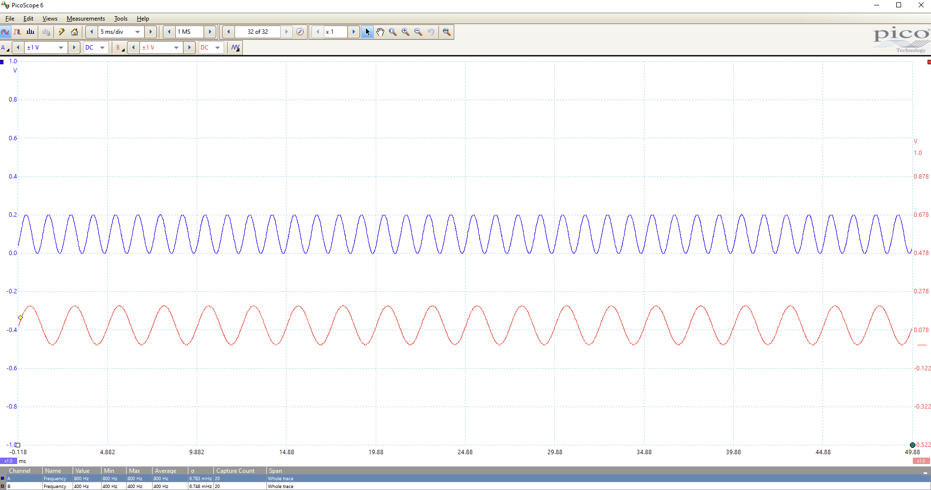
Expected and actual results
The blue trace below shows the DAC Channel A (core 1) output. The red trace shows the DAC Channel B (core 0) output. In the small text at the bottom of the image, you can see the measured frequency for each output, which is 800 and 400 Hz respectively, to within the expected error margin.
CMakeLists.txt
Note that we've linked the high-level API for multicore, and the hardware libraries for sync and spi!
add_executable(multicore_dds multicore_dds.c)

# Add pico_multicore which is required for multicore functionality
target_link_libraries(multicore_dds pico_stdlib pico_multicore hardware_sync hardware_spi)

# create map/bin/hex file etc.
pico_add_extra_outputs(multicore_dds)
Documentation
- Please see the C SDK guide and the RP2040 datasheet.
- Please see the Direct Digital Synthesis webpage
- Please see the Fixed Point Arithmetic webpage
Open questions
- How is memory shared between cores? It appears that globally declared variables are visible from both cores.
- What happens if I have two timers in an alarm pool, each configured to trigger simultaneously? Do both callback functions get called? If so, in what order?