Project code and demo
Code Organization
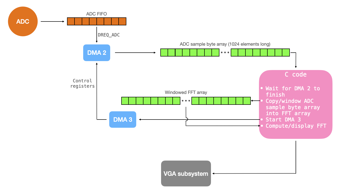
The code is structured as shown below. The ADC pacing timer is configured to gather samples at 10kHz, and to store those samples in the ADC FIFO (pre-shifted to 8 bits of significance). Whenever a sample appears in the ADC FIFO, the ADC's DREQ is asserted. DMA channel 2 is paced by the ADC DREQ, so that it automatically moves the ADC sample from the FIFO to a byte array. The DMA channel is configured to increment its write address so that it fills up each element of this 1024-element array with samples, at which point it signals to the C-code that it has finished. The C-code windows/copies this array to a local array, and then starts DMA channel 3. DMA channel 3 writes to the control registers of DMA channel 2 to reconfigure and restart it. While the next batch of samples is being gathered, the C code uses the local array to compute and display the FFT. It does so using the VGA PIO state machine described at length here.
Because details of the FFT are treated in detail in the write-up for another project (see Realtime Audio Spectrogram on PIC32), they are not treated here. The same is true for the VGA driver (see VGA driver written in PIO assembly for RP2040). This webpage instead discusses new topics, which include RP2040 ADC configuration and control with DMA.
FFT overview
Note!!: Please see one of my other webpages for a detailed description/derivation of the FFT code included below.
void FFTfix(fix fr[], fix fi[]) {

    unsigned short m;   // one of the indices being swapped
    unsigned short mr ; // the other index being swapped (r for reversed)
    fix tr, ti ; // for temporary storage while swapping, and during iteration

    int i, j ; // indices being combined in Danielson-Lanczos part of the algorithm
    int L ;    // length of the FFT's being combined
    int k ;    // used for looking up trig values from sine table

    int istep ; // length of the FFT which results from combining two FFT's

    fix wr, wi ; // trigonometric values from lookup table
    fix qr, qi ; // temporary variables used during DL part of the algorithm

    //////////////////////////////////////////////////////////////////////////
    ////////////////////////// BIT REVERSAL //////////////////////////////////
    //////////////////////////////////////////////////////////////////////////
    // Bit reversal code below based on that found here:
    // https://graphics.stanford.edu/~seander/bithacks.html#BitReverseObvious
    for (m=1; m<NUM_SAMPLES_M_1; m++) {
        // swap odd and even bits
        mr = ((m >> 1) & 0x5555) | ((m & 0x5555) << 1);
        // swap consecutive pairs
        mr = ((mr >> 2) & 0x3333) | ((mr & 0x3333) << 2);
        // swap nibbles ...
        mr = ((mr >> 4) & 0x0F0F) | ((mr & 0x0F0F) << 4);
        // swap bytes
        mr = ((mr >> 8) & 0x00FF) | ((mr & 0x00FF) << 8);
        // shift down mr
        mr >>= SHIFT_AMOUNT ;
        // don't swap that which has already been swapped
        if (mr<=m) continue ;
        // swap the bit-reveresed indices
        tr = fr[m] ;
        fr[m] = fr[mr] ;
        fr[mr] = tr ;
        ti = fi[m] ;
        fi[m] = fi[mr] ;
        fi[mr] = ti ;
    }

    //////////////////////////////////////////////////////////////////////////
    ////////////////////////// Danielson-Lanczos //////////////////////////////
    //////////////////////////////////////////////////////////////////////////
    // Adapted from code by:
    // Tom Roberts 11/8/89 and Malcolm Slaney 12/15/94 malcolm@interval.com
    // Length of the FFT's being combined (starts at 1)
    L = 1 ;
    // Log2 of number of samples, minus 1
    k = LOG2_NUM_SAMPLES - 1 ;
    // While the length of the FFT's being combined is less than the number of gathered samples
    while (L < NUM_SAMPLES) {
        // Determine the length of the FFT which will result from combining two FFT's
        istep = L<<1 ;
        // For each element in the FFT's that are being combined . . .
        for (m=0; m<L; ++m) {
            // Lookup the trig values for that element
            j = m << k ;                         // index of the sine table
            wr =  Sinewave[j + NUM_SAMPLES/4] ; // cos(2pi m/N)
            wi = -Sinewave[j] ;                 // sin(2pi m/N)
            wr >>= 1 ;                          // divide by two
            wi >>= 1 ;                          // divide by two
            // i gets the index of one of the FFT elements being combined
            for (i=m; i<NUM_SAMPLES; i+=istep) {
                // j gets the index of the FFT element being combined with i
                j = i + L ;
                // compute the trig terms (bottom half of the above matrix)
                tr = multfix(wr, fr[j]) - multfix(wi, fi[j]) ;
                ti = multfix(wr, fi[j]) + multfix(wi, fr[j]) ;
                // divide ith index elements by two (top half of above matrix)
                qr = fr[i]>>1 ;
                qi = fi[i]>>1 ;
                // compute the new values at each index
                fr[j] = qr - tr ;
                fi[j] = qi - ti ;
                fr[i] = qr + tr ;
                fi[i] = qi + ti ;
            }
        }
        --k ;
        L = istep ;
    }
ADC overview
The RP2040 has an internal SAR (Successive Approximation Register) ADC. The ADC uses an independent 48MHz clock, and a sample takes 96 cycles of this clock to complete (2us). A pacing timer can be used to reduce the speed with which samples are gathered (but any individual conversion always takes 96 cycles).
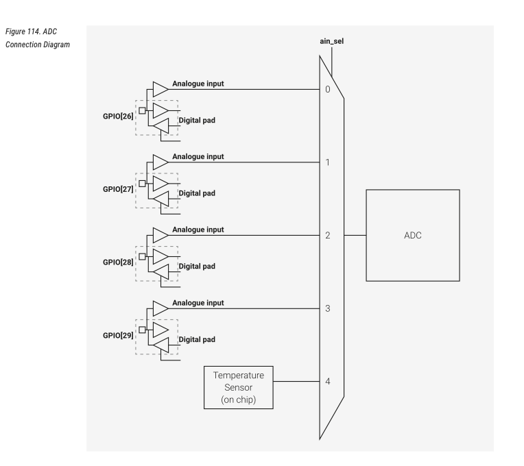
There is a 5-input MUX to the ADC, which selects among 4 GPIO ports (26, 27, 28, 29) and one internal temperature sensor. The ADC gathers 12-bit samples, with 9 effective bits. The ADC can be configured to one-shot sample mode, in which it will gather a single sample which gets stored in RESULTS. In free-running sampling mode, the ADC automatically starts new conversions at regular intervals, with the most recent conversion always availabel in RESULT. For IRQ or DMA-driven streaming, the ADC FIFO must be enabled. The FIFO is 4-entries long. If the FIFO is full when a sample completes, an error flag is set (FCS.OVER), the contents of the FIFO are not changed, and the conversion that completed when the FIFO was full is lost.
An aside on successive-approximation ADC's
A SAR ADC performs a binary search through all possible quantization levels of the ADC before converging on a digital output for the analog input.
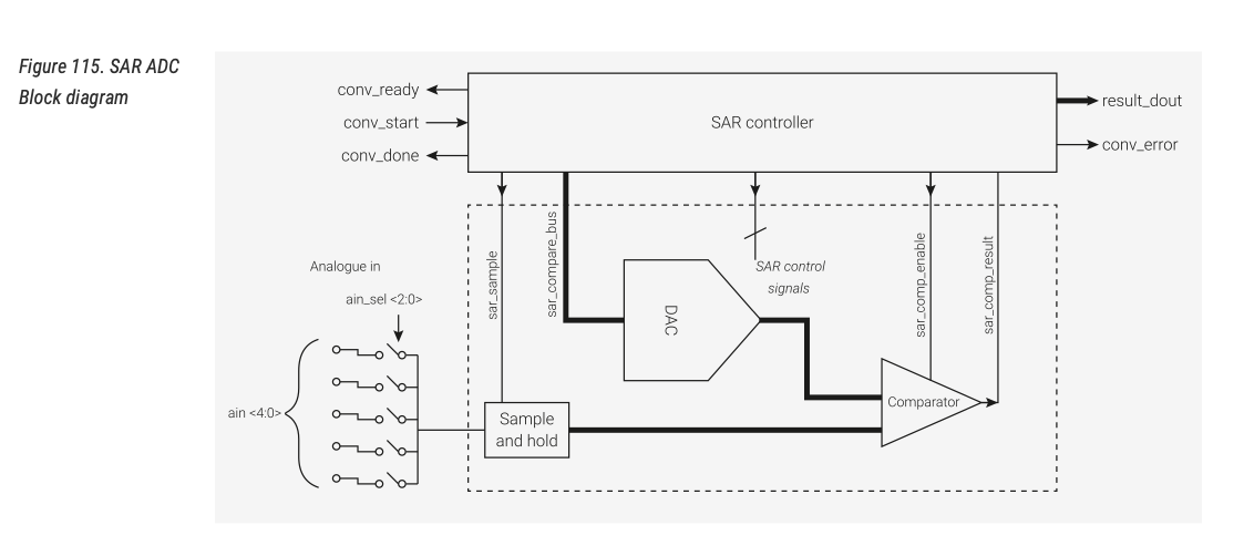
The analog input is sampled and held. This analog value is used for the positive input of a comparator, the negative input of which is attached to a DAC. This comparator compares the sampled voltage to the output of the internal DAC, the output from which is passed back to the successive approximation register. The SAR sets the most significant bit to 1, and evaluates the comparator output. If the sampled voltage is less than the DAC voltage, then the MSB is reset. Else it remains 1. The SAR then moves to the next-most significant bit and does the same. The resulting code is a digital approximation of the sampled voltage.
ADC and DMA
A series of steps are required to configure the DMA interface to the ADC. The C SDK makes these configurations quite simple, but even so care is required.
- If using a GPIO input (as opposed to the temperature sensor), prepare that GPIO for use with the ADC by disabling all digital functions. GPIO numbers 26, 27, 28, 29 are valid ADC GPIO pins.
adc_gpio_init(uint gpio) ;
- The ADC will be in an unknown state. Reset it, turn it back on, and prepare the internal 48MHz clock for use with the ADC. This is accomplished by manipulating the RESETS_RESET_ADC_BITS and ADC_CS_EN_BITS. Then, wait for ADC_CS_READY_BITS to assert, which means that the staging for the ADC is complete. In the C sdk, this is all accomplished by calling:
adc_init(void);
- Select the ADC mux input. GPIO 26 is MUX 0, 27 is MUX 1, 28 MUX 2, 29 MUX3, and temperature sensor MUX 4. This is accomplished by manipulating the AINSEL bits. In the C sdk:Note that this will select a single ADC input. If round-robin sampling of a few inputs is desired, then different configuration is required. In particular, this would involve calling the
adc_select_input(uint input) ;
adc_set_round_robin()function with the input mask. - Configure the ADC FIFO. The ADC FIFO should be turned on, the DMA data request should be enabled, DREQ (and IRQ) should be asserted when at least 1 sample is present in the FIFO, the error bit should be disabled, and the ADC should be configured to shift each sample to 8 bits when pushing to the FIFO (so that we can DMA to a byte array). This is all accomplished with the following:
// Setup the FIFO
 adc_fifo_setup(
     true,    // Write each completed conversion to the sample FIFO
     true,    // Enable DMA data request (DREQ)
     1,       // DREQ (and IRQ) asserted when at least 1 sample present
     false,   // We won't see the ERR bit because of 8 bit reads; disable.
     true     // Shift each sample to 8 bits when pushing to FIFO
 );
- Configure the pacing timer for the ADC. Divisor of 0 -> full speed. Free-running capture with the divider is equivalent to pressing the ADC_CS_START_ONCE button once per
div + 1cycles (div not necessarily an integer). Each conversion takes 96 cycles, so in general you want a divider of 0 (hold down the button continuously) or > 95 (take samples less frequently than 96 cycle intervals). This is all timed by the 48 MHz ADC clock. For example, for a sample rate $F_s$, the setup is (48Mhz/$F_s$ - 1).adc_set_clkdiv(48000000/Fs) ;
- Do not start the ADC yet. We need to setup the DMA channel first.
- Configure the DMA channel for 8-bit transfers, no read incrementing, yes write incrementing, paced by
DREQ_ADC. The DMA channel should read from&adc_hw->fifoand it should write to a byte array of lengthNUM_SAMPLES.// Channel int sample_chan = 2 ; // Channel configurations dma_channel_config c2 = dma_channel_get_default_config(sample_chan); // ADC SAMPLE CHANNEL channel_config_set_transfer_data_size(&c2, DMA_SIZE_8); // 8-bit txfers channel_config_set_read_increment(&c2, false); // no read incrementing channel_config_set_write_increment(&c2, true); // yes write incrementing channel_config_set_dreq(&c2, DREQ_ADC); // paced by DREQ_ADC // Configuration dma_channel_configure(sample_chan, &c2, // channel config sample_array, // dst &adc_hw->fifo, // src NUM_SAMPLES, // transfer count false // do not start immediately );
- Configure a second channel to reconfigure and restart the first.
// Channels
 int control_chan = 3 ;
 // Channel configurations
 dma_channel_config c3 = dma_channel_get_default_config(control_chan);
 // CONTROL CHANNEL
 channel_config_set_transfer_data_size(&c3, DMA_SIZE_32);              // 32-bit txfers
 channel_config_set_read_increment(&c3, false);                        // no read incrementing
 channel_config_set_write_increment(&c3, false);                       // no write incrementing
 channel_config_set_chain_to(&c3, sample_chan);                        // chained to sample channel
 //Configuration
 dma_channel_configure(
     control_chan,                         // Channel to be configured
     &c3,                                  // The configuration we just created
     &dma_hw->ch[sample_chan].write_addr,  // Write address (channel 0 read address)
     &sample_address_pointer,              // Read address (POINTER TO AN ADDRESS)
     1,                                    // Number of transfers, in this case each is 4 byte
     false                                 // Don't start immediately.
 );
- Start the sample channel.
dma_start_channel_mask(1u << sample_chan);
- Start the ADC.
adc_run(true) ;
- Wait for the DMA to finish.
dma_channel_wait_for_finish_blocking(sample_chan) ;
- Halt the ADC, or immediately start a new DMA transfer.
adc_run(false) ;
- Drain the FIFO.
adc_fifo_drain() ;
- Use the samples.
- Trigger the control channel, which will reconfigure and restart the sample channel.
dma_channel_start(control_chan) ;
- Restart the adc.
adc_run(true) ;
- Back to 11.